Holybro
Holybro ShopPX4 GuideArdupilot WikiContact Us
  • Welcome
  • Flight Controller
    • Pixhawk 6X
      • Overview
      • Technical Specification
      • Sample Wiring Diagram
      • Pixhawk Baseboards
      • Dimensions
        • Rev 8 (Current)
        • Rev 3 & 4
      • PX4 & Ardupilot Guide
      • Supported Firmware
      • Using Analog PM
      • Pixhawk Autopilot FMUv6X Standard
      • Download
    • Pixhawk 6X Pro
      • Overview
      • Technical Specification
      • Sample Wiring Diagram
      • Pixhawk Baseboards
      • Dimensions
      • PX4 & Ardupilot Guide
      • Supported Firmware
      • Using Analog PM
      • Pixhawk Autopilot FMUv6X Standard
      • Download
    • Pixhawk Baseboards
      • Pixhawk Baseboard v1 Ports
      • Pixhawk Baseboard v2 Ports
        • PWM Signal Voltage MOD
      • Pixhawk Baseboard V2 Mounting Plate Dimensions
      • Pixhawk Mini Baseboard Ports
      • Pixhawk Jetson Baseboard
        • Overview & Specification
        • Ports Pinout
        • Wiring & Block Diagram
        • Dimension & Weight
        • Flashing guide
        • CAN setup
        • CSI Camera setup
        • MAVLINK Bridge
        • Reference Links
      • Pixhawk RPi CM4 Baseboard
        • Overview
        • Connections & Ports
        • RPi CM4 Flash Guide
        • Dimension
        • Ethernet Connection
        • PM03D - RPi CM4 Base Wiring Guide
        • Installation of RPi CM4
        • Supported Firmware
      • Baseboard Changelog
      • Download
    • Pixhawk 6C
      • Overview
      • Technical Specification
      • Pixhawk 6C Ports
      • Sample Wiring Diagram
      • Dimensions
      • System Diagram & Pinout
      • PX4 & Ardupilot Guide
      • PWM Signal Voltage MOD
      • Supported Firmware
      • Download
    • Pixhawk 6C Mini
      • Overview
      • Technical Specification
      • Pixhawk 6C Mini Ports
      • Dimensions
      • System Diagram & Pinout
      • PWM Signal Voltage MOD
      • Supported Firmware
      • Pixhawk 6C Mini Difference
      • Download
    • Pix32 v6
      • Overview
      • Technical Specification
      • Pix32 v6 Baseboard Ports
      • Pix32 v6 Mini-Base Ports
      • Dimensions
      • System Diagram & Pinout
      • Supported Firmware
      • Download
    • Durandal
      • Overview & Technical Specification
      • Dimensions
      • Durandal Pinout
      • Supported Firmware
    • Kakute H7 (v1/v2/Mini)
      • Kakute H7 v1
        • Overview
        • Wiring Diagram
        • Pinout
        • Supported Firmware
      • Kakute H7 v2
        • Overview
        • Wiring Diagram
        • Pinout
        • Supported Firmware
          • INAV VTX+ & Bluetooth Setup
      • Kakute H7 Mini
        • Overview
        • Sample Wiring Diagram
        • Pinout
        • Supported Firmware
      • Kakute H7 Version Difference
      • Download
    • Kakute H743-Wing
      • Overview
      • Pinout
      • Sample Wiring Diagram
      • Power Monitor & Scale
      • Camera & ON/OFF Pit Switch
      • Ardupilot Mapping
      • Ardupilot Wiki
      • INAV Mapping
      • Supported Firmware
    • Kakute F405 Wing Mini
      • Overview
      • Pinout
      • Sample Wiring Diagram
      • Power Monitor & Scale
      • Supported Firmware
    • Autopilot Comparison
  • GPS & RTK System
    • H-RTK NEO-F9P Series (RM3100 Compass)
      • Overview
      • Specification
      • NEO-F9P Module Pinout
      • NEO-F9P Rover Pinout
      • Dimensions
      • Downloads
      • Setup & Getting Started
      • Firmware Upgrade
      • GPS Heading/Yaw (aka Moving Baseline)
      • Setup guide for Multiple Aircraft
      • Portable RTK Base Station Setup
      • CAN Termination Resistance Software Toggle
    • H-RTK ZED-F9P Series (RM3100 Compass)
      • Overview
      • Specification
      • Dimension
      • Pinout
      • Download
      • Setup & Getting Started (Ardupilot)
      • Setup & Getting Started (PX4)
      • Using with Cube Autopilot
      • u-blox F9P Firmware Upgrade
      • DroneCAN FW Upgrade
      • GPS Heading/Yaw (aka Moving Baseline)
      • Setup guide for Multiple Aircraft
      • Portable RTK Base Station Setup
      • Galileo OSNMA Support
      • Changelog
      • CAN Termination Resistance Software Toggle
    • H-RTK ZED-F9P Series (IST8310/BMM150 Compass)
      • DroneCAN F9P
        • Overview
        • Specification
        • Pinout
        • Dimension
        • Setup & Getting Started
        • DroneCAN FW Upgrade
        • Download
        • CAN Termination Resistance Software Toggle
      • Standard F9P (UART)
        • Overview
        • F9P Rover Lite
        • F9P Helical
        • F9P Base
        • H-RTK with Cube Autopilot
        • Specification & Comparison
        • Setup & Getting Started
        • Dimension
        • Pinout
        • Download
      • u-blox F9P Firmware Upgrade
      • GPS Heading/Yaw (aka Moving Baseline)
      • Setup guide for Multiple Aircraft
      • Ardupilot IST8310 Compass Orientation
      • Portable RTK Base Station Setup
      • Galileo OSNMA Support
    • H-RTK Unicore UM982
      • Overview
      • Specification
      • Pinout
      • Dimension
      • LED Indicator
      • Setup & Getting Started (Ardupilot)
      • Setup & Getting Started (PX4)
      • Advanced Application (Unicore Uprecise)
      • Factory Setting and COM Port Allocation
      • Firmware Support
      • Download
    • H-RTK mosaic-H
      • Overview & Specification
      • Setup & Getting Started (Ardupilot)
      • Setup & Getting Started (PX4)
      • Pinout
      • Dimension
      • Advanced Application
      • GPS LED Meaning
      • Septentrio PPK application
      • Septentrio receiver control and analysis software
      • Supported Firmware
      • Download
    • M8N/M9N/M10 GPS
      • Standard M10/M9N/M8N GPS
        • Overview
        • Pinout
        • Dimension
        • Download
      • Micro M10/M9N GPS
        • Overview
        • Pinout
        • Dimension
        • Download
      • DroneCAN M9N/M8N
        • Overview
        • Pinout
        • Dimension
        • DroneCAN GPS Setup Guide
        • DroneCAN FW Upgrade
        • CAN Termination Resistance Software Toggle
        • About DroneCAN
        • Downloads
      • Ardupilot IST8310 Compass Orientation
      • Downloads
    • GPS LED & Buzzer
      • GPS LED & Buzzer Meaning
      • Status LED Changes
  • Peripherals
    • DLVR Airspeed (DroneCAN)
      • Overview
      • Quick Start Guide
      • CAN Termination Resistance Software Toggle
      • Download
    • MS4525DO & MS5525DSO I2C Airspeed Sensor
    • RM3100 Compass (DroneCAN)
      • RM3100 Setup Guide
      • CAN Termination Resistance Software Toggle
    • H-Flow (DroneCAN)
      • Overview
      • Setup Guide
      • Firmware
      • Dimensions
      • Pinout
      • CAN Termination Resistance Software Toggle
      • Downloads
  • PMW3901 Optical Flow Sensor
  • CAN Termination Resistance Software Toggle
  • Radio
    • Remote ID
      • Overview & Spec
      • Setup & Configuration
      • Pinout
      • Firmware Support
      • Firmware Update
      • Download
    • SiK Telemetry Radio V3
      • LED and Connection
      • Multiple Point to Point Setup with Sik Radio
        • Downloads
    • Microhard Radio
      • Overview
      • Specification
      • Ports & Buttons
      • Status LED
      • Default Setting
      • Pinout
      • Dimension
      • Enabling RTS / CTS Flow Control
      • Point-to-Multipoint Setup with Microhard Radio
      • Download
    • XBP9X Radio
      • Specification
      • Power
      • Status LEDs
      • Antenna
      • Pinout
      • Dimension
      • Point-to-Multipoint Setup with XBee Radio
      • Download
  • Drone Development Kit
    • X650 Development Kit
      • NeoPixel WS2812 LED Setup Instruction
      • Download
    • PX4 Development Kit - X500v2
      • Getting Started Build Guide
      • Download
    • PX4 Vision Dev Kit v1.5
      • Overview
      • Wiring Diagram
      • v1 & v1.5 Difference
      • Up-Core Carrier Board Pinout
      • PX4 User Guide
      • Downloads
    • S500 Frame Kit
  • Power Module & PDB
    • Power Module
      • DroneCAN Power Module Setup
      • Analog Power Module Setup
      • Digital Power Module (PM) Setup
      • PM07 Quick Start Guide
      • Using Analog PM with Pixhawk 5X/6X
      • Connector & Wire Rating
      • Download
    • Power Module Comparison
  • UBEC
  • ESC
    • ESC Current Sensor Scale
    • AM32 ESC - Reverse Motor Direction Instruction
    • How To Flash AM32 Firmware To HOLYBRO BLHeli ESCs
  • ESC 3D File Downloads
  • Company
    • About Us
    • Holybro Logo
    • Certification (ISO, FCC, CE, RoHS, etc):
    • User Manuals
      • Kakute Flight Controller
      • ESC
      • Kopis
      • Autopilot Flight Controller
      • Drone Dev Kit
      • Other
Powered by GitBook

© 2024 Holybro. All rights reserved.

On this page

Was this helpful?

Export as PDF
  1. Flight Controller
  2. Pixhawk Baseboards
  3. Pixhawk RPi CM4 Baseboard

Ethernet Connection

PreviousDimensionNextPM03D - RPi CM4 Base Wiring Guide

Last updated 1 year ago

Was this helpful?

Link-local networking setup between CM4 and FC
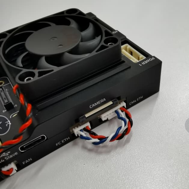
Local cable

To set up a local ethernet connection between CM4 and the flight computer, the two ethernet ports need to be connected using a 8 pin to 4 pin connector.

The pinout of the cable is:

8 pin: 1 A 2 B 3 C 4 D 5 (not connected) 6 (not connected) 7 (not connected) 8 (not connected)

to 4 pin: 1 B 2 A 3 D 4 C

IP setup on CM4

Since there is no DHCP server active in this configuration, the IPs have to be set manually: First, connect to the CM4 via ssh by connecting to the CM4’s wifi (or use a Wifi dongle). Once the ethernet cables are plugged in, the eth0 network interface seems to switch from DOWN to UP.

You can check the status using:

ip address show eth0

You can also try to enable it manually:

sudo ip link set dev eth0 up

It then seems to automatically set a link-local address, for me it looks like this:

ip address show eth0

2: eth0: <BROADCAST,MULTICAST,UP,LOWER_UP> mtu 1500 qdisc mq state UP group default qlen 1000
    link/ether xx:xx:xx:xx:xx:xx brd ff:ff:ff:ff:ff:ff
    inet 169.254.21.183/16 brd 169.254.255.255 scope global noprefixroute eth0
       valid_lft forever preferred_lft forever
    inet6 fe80::yyyy:yyyy:yyyy:yyyy/64 scope link 
       valid_lft forever preferred_lft forever

This means the CM4’s ethernet IP is 169.254.21.183.

IP setup on FC

Now connect to the NuttX shell (using a console, or the MAVLink shell), and check the status of the link:

ifconfig

eth0    Link encap:Ethernet HWaddr xx:xx:xx:xx:xx:xx at DOWN
        inet addr:0.0.0.0 DRaddr:192.168.0.254 Mask:255.255.255.0

For me it is DOWN at first.

To set it to UP:

ifup eth0

ifup eth0...OK

Now check the config again:

ifconfig

eth0    Link encap:Ethernet HWaddr xx:xx:xx:xx:xx:xx at UP
        inet addr:0.0.0.0 DRaddr:192.168.0.254 Mask:255.255.255.0

However, it doesn’t have an IP yet. I’m going to set one similar to the one of CM4:

ifconfig eth0 169.254.21.184

And check it:

ifconfig

eth0    Link encap:Ethernet HWaddr xx:xx:xx:xx:xx:xx at UP
        inet addr:169.254.21.184 DRaddr:169.254.21.1 Mask:255.255.255.0

Now the devices should be able to ping each other.

Note that this configuration is ephemeral and will be lost after a reboot, so we’ll need to find a way to configure it statically.

Ping test

First from the CM4:

ping 169.254.21.184

PING 169.254.21.184 (169.254.21.184) 56(84) bytes of data.
64 bytes from 169.254.21.184: icmp_seq=1 ttl=64 time=0.188 ms
64 bytes from 169.254.21.184: icmp_seq=2 ttl=64 time=0.131 ms
64 bytes from 169.254.21.184: icmp_seq=3 ttl=64 time=0.190 ms
64 bytes from 169.254.21.184: icmp_seq=4 ttl=64 time=0.112 ms
^C
--- 169.254.21.184 ping statistics ---
4 packets transmitted, 4 received, 0% packet loss, time 3077ms
rtt min/avg/max/mdev = 0.112/0.155/0.190/0.034 ms

And from the FC in Nuttx Shell:

ping 169.254.21.183

PING 169.254.21.183 56 bytes of data
56 bytes from 169.254.21.183: icmp_seq=0 time=0 ms
56 bytes from 169.254.21.183: icmp_seq=1 time=0 ms
56 bytes from 169.254.21.183: icmp_seq=2 time=0 ms
56 bytes from 169.254.21.183: icmp_seq=3 time=0 ms
56 bytes from 169.254.21.183: icmp_seq=4 time=0 ms
56 bytes from 169.254.21.183: icmp_seq=5 time=0 ms
56 bytes from 169.254.21.183: icmp_seq=6 time=0 ms
56 bytes from 169.254.21.183: icmp_seq=7 time=0 ms
56 bytes from 169.254.21.183: icmp_seq=8 time=0 ms
56 bytes from 169.254.21.183: icmp_seq=9 time=0 ms
10 packets transmitted, 10 received, 0% packet loss, time 10010 ms

MAVLink/MAVSDK test

For this, we need to set the mavlink instance to send traffic to the CM4’s IP:

For an initial test we can do:

mavlink start -o 14540 -t 169.254.21.183

This will send MAVLink traffic on UDP to port 14540 (the MAVSDK/MAVROS port) to that IP which means MAVSDK can just listen to any UDP arriving at that default port.

For instance:

python3 -m pip install mavsdk

wget https://raw.githubusercontent.com/mavlink/MAVSDK-Python/main/examples/tune.py
chmod +x tune.py
./tune.py

To run a MAVSDK example, install mavsdk via pip, and try out an example from .

MAVSDK-Python/examples
LogoGet the Pixhawk Raspberry Pi CM4 Baseboard by Holybro talking with PX4 - PX4 AutopilotPX4 Autopilot