This documentation will help you understand Holybro's official product introduction, technical specifications, pinout, tutorials, assembly, etc.
If you have any comments or suggestions on our documentation, please send an email to Support@holybro.com
These baseboard is compatible with both Pixhawk 5X & 6X, and any flight controller that follow the Pixhawk Bus Standard.
Kakute H7 (v1/v2/Mini)
Overview
Inside the Pixhawk® 6X, you can find an STMicroelectronics® based STM32H753, paired with sensor technology from Bosch®, InvenSense®, giving you flexibility and reliability for controlling any autonomous vehicle, suitable for both academic and commercial applications.
The Pixhawk® 6X’s H7 microcontroller contains the Arm® Cortex®-M7 core running up to 480 MHz, has 2MB flash memory and 1MB RAM. The PX4 takes advantage of the increased power and RAM. Thanks to the updated processing power, developers can be more productive and efficient with their development work, allowing for complex algorithms and models.
The FMUv6X open standard includes high-performance, low-noise IMUs on board, designed for better stabilization. Triple redundant IMU & double redundant barometer on separate buses. When the PX4 detects a sensor failure, the system seamlessly switches to another to maintain flight control reliability.
An independent LDO powers every sensor set with independent power control. A vibration isolation System to filter out high-frequency vibration and reduce noise to ensure accurate readings, allowing vehicles to reach better overall flight performances.
External sensor bus (SPI5) has two chip select lines and data-ready signals for additional sensors and payload with SPI-interface, and with an integrated Microchip Ethernet PHY, high-speed communication with mission computers via ethernet is now possible.
The Pixhawk® 6X is perfect for developers at corporate research labs, startups, academics (research, professors, students), and commercial application.
Key Design Points
High-performance STM32H753 Processor
Modular flight controller: separated IMU, FMU, and Base system connected by a 100-pin & a 50-pin Pixhawk® Bus connector.
Redundancy: 3x IMU sensors & 2x Barometer sensors on separate buses
The previous shipped "Rev3 & 4" has different dimension compared to the "Rev8".
Rev3 & 4
Pixhawk 5X & 6X Flight Controller Module
Standard Baseboard
Pixhawk Baseboard
Mini Baseboard
Pixhawk Mini Baseboard
Wiring Diagram
Part 1
Part 2
Wiring Diagram
Sample Wiring Diagram
Dimension
Rev 8 (Current)
Dimension in Millimeters
This version is currently being shipped.
FC Module Only
Standard Baseboard v2A
Mini Baseboard
Standard Baseboard v1
CSI Camera setup
Popular cameras supported out of the box include IMX219 camera modules, such as the Raspberry Pi Camera Module V2. For the CSI camera, basically you could benefit from the Nvidia guide
You may need to connect your Jetson to a display before attempting NVIDIA's CSI camera guide.
The Holybro Jetson carrier board can have two CSI cameras connected. To give a short intro, you can try the following commands in the terminal in case your carrier board is connected to a display screen:
nvgstcapture-1.0
To open the capture on a specific CAM, you can pass the following (assuming we want to test cam1 on Orin_camera 1):
nvgstcapture-1.0 sensor-id=1
Reference Links
PX4
Ardupilot
Helper Scripts
Supported Firmware
Pixhawk 6X Pro is shipped with PX4 FMUv6X Firmware, but it is also supported in Ardupilot. It shares the same firmware as Pixhawk 6X.
Pixhawk 6X Pro is supported on Master/Main or PX4 1.14.3 release and later.
PX4 Firmware Target: FMUv6x
Pixhawk 6X Pro is supported in Ardupilot 4.5.0 stable release and later. Ardupilot Firmware Target: Pixhawk 6X. Ardupilot firmware can be flash via Mission Planner or QGroundControl.
It can also be downloaded here: https://firmware.ardupilot.org/
Dimensions
Dimension in millimeters
Pixhawk 6C Mini Model A (Current)
Pixhawk 6C Mini Model B
Dimension for discontinued version Model A
Pixhawk 6C Mini Model A (Legacy)
CAN setup
CAN2 on the basboard is conneted internally to both FCU and Jetson module. The basics could be implemented from Nvidia user guide:
However, you could follow the below quick commands might make you able to loopback test the CAN connection between Jetson module and FCU on Jetson's terminal:
sudo modprobe mttcan
sudo ip link set can0 type can bitrate 500000 loopback on
sudo ip link set can0 up
candump can0 &
cansend can0 123#abcdabcd
The last command has to have the following output if can is running OK:
can0 123 [4] AB CD AB CD
can0 123 [4] AB CD AB CD
Sample Wiring Diagram
Pixhawk Baseboard V2 Mounting Plate Dimensions
V2A
V2B
Wiring & Block Diagram
Block Diagram
Reference Wiring Diagram
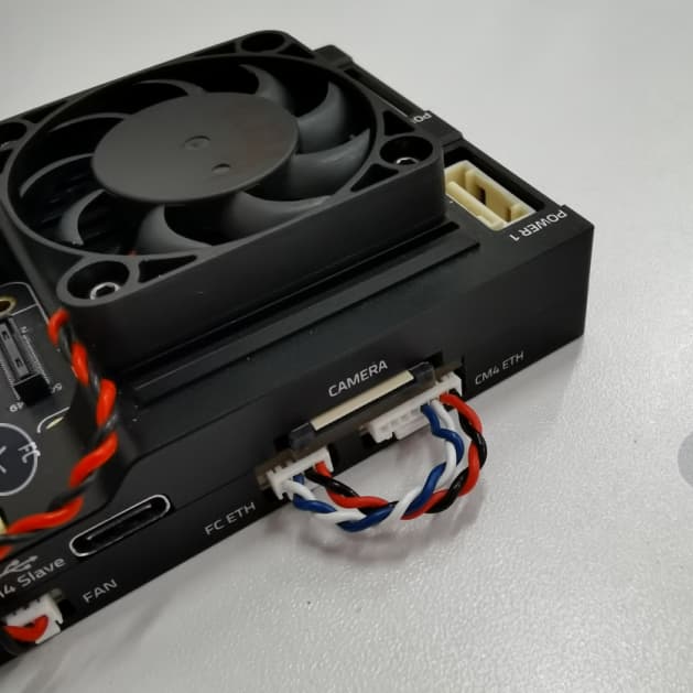
PM03D - RPi CM4 Base Wiring Guide
To ensure stable power supply, the RPi CM4 & Flight controller must be powered separately.
Flight controller is powered via the CLIK-Mate cable to POWER1 or POWER2 port, and RPi CM4 is powered by the USB C (CM4 Slave) connection.
Dimensions
Dimension in millimeters
PWM Signal Voltage MOD
The newest batch (version RC09 and newer) of Pixhawk 6C now supports switchable PWM signal voltage (3.3V or 5V). The modification requires the user to open the casing of the Pixhawk flight controller and be familiar with soldering.
Any damages caused during the modification are not covered by warranty
To switch the PWM signal voltage, bridge the 3V3 or 5V soldering pads on the PCB by applying solder on the pads. Make sure the unused pads are cleaned and not shorted.
RC09 PCB
For RC12 PCB design, the process is more straightforward. Locate the JP1 soldering pad at the bottom left of the PCB. Bridge the JP1 pads for 5V and unbridge to revert to 3.3V.
RC12
System Diagram & Pinout
Pixhawk 6C & Pix32 v6 shares the same System Diagram & Pinout
If you are using PX4, please refer to the PX4 user guide page for additional information.
If you are using Ardupilot, please refer to the Ardupilot user guide page for additional information.
Sample Wiring Diagram
Dimensions
Dimension in millimeters
Pixhawk Baseboard
Pixhawk Mini Baseboard
PX4 & Ardupilot Guide
If you are using PX4, please refer to the PX4 user guide page for additional information.
If you are using Ardupilot, please refer to the Ardupilot user guide page for additional information.
Sample Wiring Diagram
Overview
Pixhawk 6X with the Pixhawk RPi CM4 Baseboard
The Holybro Pixhawk RPi CM4 Baseboard combine the Pixhawk FC module with the Raspberry Pi CM4 companion computer in on compact form factor with all the connections you need for development.
It follows the Pixhawk Connector and Bus Standard, allow easy swap of FC Module with any FC that follows the Pixhawk Bus Standard. The FC Module is internally connected to RPi CM4 through TELEM2, and can also be connected via ethernet with a external cable provided.
Recommend minimum specification for RPi CM4:
Wireless: Yes
RAM: 4GB (or 8GB)
eMMC: 16GB
PX4 & Ardupilot Guide
Pixhawk 6X Pro share the same target as Pixhawk 6X
PX4
If you are using PX4, please refer to the PX4 user guide page for additional information.
Ardupilot
If you are using PX4, please refer to the PX4 user guide page for additional information.
Supported Firmware
Supported on PX4 v1.11.0 and later.
Supported in Ardupilot 4.0 and later.
Dimension & Weight
Outer alloy case weight: 90g
Without Jetson and Flight Controller: 85g
With Jetson, no Heatsink or Flight Controller: 110g
Supported Firmware
Betaflight Target: KAKUTEH7
INAV Target: KAKUTEH7
Ardupilot Target:
PX4: (PX4 v1.13 or later)
Firmware can be built using make holybro_kakuteh7
PX4 Bootloader HEX file for KakuteH7 (v1):
INAV VTX+ & Bluetooth Setup
Holybro Kakute H7 V2 PINIO Setup for INAV 5.1 This manual applies to INAV 5.1, Holybro Kakute H7 V2 and covers the topic of PINIO functionality setup so that following goals are achieved:
Built in Bluetooth is active when INAV is NOT armed
Built in Bluetooth is disabled when INAV is armed
Supported Firmware
Betaflight Target: KAKUTEH7MINI
INAV Target: KAKUTEH7MINI
v1.2 & prior: KakuteH7Mini
v1.3: KakuteH7Mini-Nand
PWM Signal Voltage MOD
The newest batch of Pixhawk baseboard V2 now supports switchable PWM signal voltage (3.3V or 5V). The modification requires the user to open the casing of the Pixhawk flight controller and be familiar with soldering.
To switch the PWM signal voltage, bridge the 3v3 or 5v soldering pads on the PCB by applying solder on the pads. Make sure the unused pads are cleaned and not shorted.
Pixhawk baseboard V2-A and V2-B have slightly different PCB designs. Follow the red square in the diagram below to locate the PWM voltage select soldering pad.
A newer design that provides a more stable voltage signal and easier modding process is currently available.
Find the JP1 on the PCB (default with no resistor soldered at the location), leave the spot empty for 3.3V signal voltage, and short the two soldering pads for 5V.
Installation of RPi CM4
To install Raspberry Pi CM4 companion compute onto this baseboard.
Disconnect the FAN connector.
Remove these 4 screws on the back side of the baseboard.
Supported Firmware
Support in PX4 1.14.3 release and later.
Supported in 4.5.0 stable release and later.
Pixhawk 6X is supported on PX4 and later.
Supported in Ardupilot 4.2.3 stable release and later.
Overview
Key Design Point
High-performance ADIS16470 Industrial IMU with high accelerometer dynamic range (±40 g), perfect for accurate motion sensing in demanding UAV applications
All New advanced durable vibration isolation material with resonance frequency in the higher spectrum, ideal for industrial and commercial drone applications
Pixhawk 6C Mini Difference
These ports are not available in the Pixhawk 6C Mini (compared to the "standard" Pixhawk 6C):
Power2 Port
Telem3 Port
Supported Firmware
Pixhawk 6C Mini is supported on PX4 and later.
Pixhawk 6C Mini is supported in Ardupilot 4.2.3 stable release and later. Firmware can be flash via Mission Planner or QGroundControl. It can also be downloaded here:
Must use or later, or .
Overview
The Pixhawk® 6C Mini is the latest update to the successful family of Pixhawk® flight controllers, based on the and . It shares the same STMH743 microprocessor and sensors as the Pixhawk 6C. Compared to the standard Pixhawk 6C, this Mini version has a built-in PWM header, and some ports have been removed in order to fit this Mini form factor.
Inside the Pixhawk® 6C Mini, you can find an STMicroelectronics®-based STM32H743, paired with sensor technology from Bosch® & InvenSense®, giving you flexibility and reliability for controlling any autonomous vehicle, suitable for both academic and commercial applications.
The Pixhawk® 6C Mini's H7 microcontroller contains the Arm® Cortex®-M7 core running up to 480 MHz and has 2MB flash memory and 1MB RAM. Thanks to the updated processing power, developers can be more productive and efficient with their development work, allowing for complex algorithms and models.
The FMUv6C open standard includes high-performance, low-noise IMUs on board, designed to be cost-effective while having IMU redundancy. A vibration isolation system to filter out high-frequency vibration and reduce noise to ensure accurate readings, allowing vehicles to reach better overall flight performances.
Baseboard Changelog
Smaller and More Compact Design: The overall footprint of the board has been reduced, making it easier to integrate into various applications.
New Robust Pin Header Design: Improved reliability with a improved pin header housing.
Added PWM Level Shifter: Allows PWM output signal levels to be switched from 3.3V to 5V via a resistor or solder bridge.
Supported Firmware
Pix32v6 is supported on PX4 and later.
Pix32 v6 (with SN number higher than XXXX XXX 20221112) requires or later.
Pix32 v6 is supported in Ardupilot 4.2.3 stable release and later. It uses the "Pixhawk 6C" Firmware Target. Firmware can be flash via Mission Planner or QGroundControl. It can also be downloaded here:
Must use or later, or .
Overview
The Pixhawk® 6C is the latest update to the successful family of Pixhawk® flight controllers, based on the and . It comes with PX4® pre-installed.
Inside the Pixhawk® 6C, you can find an STMicroelectronics® based STM32H743, paired with sensor technology from Bosch® & InvenSense®, giving you flexibility and reliability for controlling any autonomous vehicle, suitable for both academic and commercial applications.
The Pixhawk® 6C’s H7 microcontroller contain the Arm® Cortex®-M7 core running up to 480 MHz, has 2MB flash memory and 1MB RAM. Thanks to the updated processing power, developers can be more productive and efficient with their development work, allowing for complex algorithms and models.
Download
Overview
The Pix32 v6 is the latest update to the pix32 v5 flight controllers. It is a variant of the Pixhawk 6C. It is comprised of a separate flight controller and carrier board which are connected by a . It is designed for those pilots who need a high power, flexible and customizable flight control system.
Inside the Pix32 v6, you can find an STMicroelectronics® based STM32H743, paired with sensor technology from Bosch® & InvenSense®, giving you flexibility and reliability for controlling any autonomous vehicle, suitable for both academic and commercial applications.
The Pix32 v6’s H7 microcontroller contain the Arm® Cortex®-M7 core running up to 480 MHz, has 2MB flash memory and 1MB RAM. Thanks to the updated processing power, developers can be more productive and efficient with their development work, allowing for complex algorithms and models. It includes high-performance, low-noise IMUs on board, designed to be cost effective while having IMU redundancy. A vibration isolation System to filter out high-frequency vibration and reduce noise to ensure accurate readings, allowing vehicles to reach better overall flight performances.
Supported Firmware
Pixhawk 6C is supported on PX4 and later.
Pixhawk 6C is supported in Ardupilot 4.2.3 stable release and later. Firmware can be flash via Mission Planner or QGroundControl. It can also be downloaded here:
Must use or later, or .
Download
PWM Signal Voltage MOD
The newest batch of Pixhawk 6C mini now supports switchable PWM signal voltage (3.3V or 5V). The modification requires the user to open the casing of the Pixhawk flight controller and be familiar with soldering.
Once you remove the top half of the flight controller casing, you'll notice the ribbon connector with silicone glue along its sides. The connector isn't fully adhered to, so it can be detached with a small amount of force. After removing the ribbon connector, you'll have safe access to the back side of the PCB for making modifications to the PWM signal voltage.
To switch the PWM signal voltage, bridge the 3v3 or 5v soldering pads on the PCB by applying solder on the pads. Make sure the unused pads are cleaned and not shorted.
For Pixhawk 6C mini, you have the option to change the PWM signal voltage for FMU outputs and IO outputs separately. Make sure the correct soldering pads are bridged to avoid any damage.
Pixhawk 6C mini-A (legacy) and mini-B have slightly different PCB designs. Follow the red square in the diagram below to locate the PWM voltage select soldering pad.
Pix32 v6 is compatible with Pix32 v5 Baseboard and vice versa.
There are some port that will be non-functional when using a Pix32 v6 FC on a Pix32 v5 Baseboard. Please refer to Pix32 v6 Baseboard Ports & Pix32 v6 Mini-Base Portsfor more Detail
Pix32 v6 Flight Controller Module
Pix32 v5 Baseboard & Pix32 v5 Mini Baseboard Dimension
Pix32 v6 Baseboard
The Pixhawk® 6C Mini is perfect for developers at corporate research labs, startups, academics (research, professors, students), and commercial applications.
Key Design Points
High performance STM32H743 Processor with more computing power & RAM
New cost-effective design in a small form factor
IMU redundancy with sensor technology from Bosch® & InvenSense®
Integrated vibration isolation system to filter out high frequency vibration and reduce noise to ensure accurate readings
IMUs are temperature-controlled by onboard heating resistors, allowing optimum working temperature of IMUs
The FMUv6C open standard includes high-performance, low-noise IMUs on board, designed to be cost effective while having IMU redundancy. A vibration isolation System to filter out high-frequency vibration and reduce noise to ensure accurate readings, allowing vehicles to reach better overall flight performances.
The Pixhawk® 6C is perfect for developers at corporate research labs, startups, academics (research, professors, students), and commercial application.
Key Design Points
High performance STM32H743 Processor with more computing power & RAM
New cost-effective design with low-profile form factor
Newly designed integrated vibration isolation system to filter out high frequency vibration and reduce noise to ensure accurate readings
IMUs are temperature-controlled by onboard heating resistors, allowing optimum working temperature of IMUs
With Jetson Orin NX + Heatsink/Fan & FC Module: 126 x 80 x 38.6mm
Alloy case: 130 x 84 x 20mm
Without Jetson Orin & Controller
With Jetson Orin, Heatsink+Fan, and Pixhawk 6X
Jstson baseboard alloy case dimension
Weight
Dimensions
VTX is always enabled or activated on a switch
In this scenario, arming is assigned to Channel 5. USER1 mode, which drives the Bluetooth module is assigned to the same channel. When INAV is armed, USER1 is enabled as well and disables Bluetooth
To set VTX+ pad to be always powered, configured USER2 Mode to be always enabled like below.
In this scenario, VTX+ is ON only when Channel 6 is in HIGH position.
VTX+ is Default ON, to set VTX+ to turn OFF via switch, assign a channel to turn off VTX. In this scenario, VTX is OFF only when Channel 6 is in HIGH position.
Arming and Bluetooth setup
For INAV 5.1
VTX+ is Default OFF
VTX+ on a switch
For INAV 6.0 and later
V2B RC03
Any damages caused during the modification are not covered by warranty
For V2A RC12 & V2B RC02
For V2A RC13 & V2B RC03
Pixhawk Baseboard V2-A
Pixhawk Baseboard V2-B
V2A RC13
Remove the case of the baseboard, install the CM4, and screw on the 4 screws (M2x4mm).
High performance STM32H753 Processor
Ethernet interface for high-speed mission computer integration
Triple redundant IMU & double redundant barometer on separate buses
Modular flight controller: separated IMU, FMU, and Base system
Safety-driven design incorporates sensors from different manufacturers and model lineups
Independent LDO powers every sensor set with independent power control.
Temperature-controlled IMU board, allowing optimum working temperature of IMUs
Features
SBUS Out Port
IO Debug Port
4pin USB Port (JST-GH)
FMU PWM CH7 & CH8
The Pixhawk 6C Mini has built in PWM Header while the "Standard" Pixhawk 6C has a separate PWM Breakout Board.
Below are the main difference between Pixhawk 6C and Pixhawk 6C Mini
Ports
PWM Header
Change to Aluminum CNC Case: High-quality aluminum CNC outer case offers durability, efficient heat dissipation, corrosion resistance, aesthetic appeal, and EMI shielding.
Two Models Available: Model A and Model B, each with the pin header facing different directions for more flexibility in installation.
Relocated of Ports: UART4 & I2C, SPI, AD & IO, DSM RC, and JST USB ports have been moved from the top to the side of the board. AUX7, AUX8, and SBUS_OUT/RSSI_IN move to the side in a JST-GH Port.
Refer to these ports pinout page for more detail:
Pixhawk Baseboard v1 to v2
The Pixhawk Baseboard v1 has been replaced by the v2A & v2B, with the following updates
This flight controller is perfect for people that is looking for a affordable and modular flight controller that can use a customized baseboard. We have made the
, you can either make a custom carrier board yourself or just let us help you with it. By using a customize baseboard, you can make sure that the physical size, pinouts and power distribution requirements match your vehicle perfectly, ensuring that you have all the connections you need and none of the expense and bulk of connectors you don’t.
Key Design Points
High performance STM32H743 Processor with more computing power & RAM
New cost-effective design with low-profile form factor
Newly designed integrated vibration isolation system to filter out high frequency vibration and reduce noise to ensure accurate readings
IMUs are temperature-controlled by onboard heating resistors, allowing optimum working temperature of IMUs
The Holybro Kakute H7 v2 Flight Controller is full of features including integrated Bluetooth, HD camera plug, dual plug-and-play 4in1 ESC ports, 9V VTX ON/OFF Pit Switch, barometer, OSD, 6x UARTs, 128MB Flash for Logging, 5V and 9V BEC, and bigger soldering pad with easy layout and much more.
The Kakute H7 v2 builds upon the best features of its F7 predecessor and further improves on hardware components and layout. With the additional integrated Bluetooth chip onboard, you can perform configuration and tuning wirelessly on your phone with the SpeedyBee Android & IOS App. The Kakute H7 is DJI HD ready. It has an easy plug-and-play port with an on-board 9V regulator designed to power your HD video transmitter such as the DJI/Caddx FPV Air Unit & Caddx Vista while supporting analog system.
It features an onboard “VTX ON/OFF Pit Switch” that allows you to completely power off the video transmitter using a switch on your RC transmitter. Great if you are working on your drone, waiting for the GPS to get a fix, getting ready for a race while preventing it from overheating or interfering with others flying. It has 6x dedicated UART ports with built-in inversion for peripherals (UART2 is used for Bluetooth telemetry), a 128 MB Flash for logging, Dual plug-and-play 4in1 ESC connectors, allowing easy plug-and-play support for x8 & Octocopter configuration and keeping it simple and clean.
The integrated BetaFlight OSD makes it easy to display important information on your FPV display like battery voltage, flight time, warnings, RSSI, smart audio features and more. It is also ready for autonomous flight with the on-board barometer. There are LED & buzzer pad, I2C pad (SDA & SCL) for external GPS/Magnetometers. The integrated BetaFlight OSD makes it easy to display important information on your FPV display like battery voltage, flight time, warnings, RSSI, smart audio features and more. It is also ready for autonomous flight with the on-board barometer. There are LED & buzzer pad, I2C pad (SDA & SCL) for external GPS/Magnetometers.
Specification:
MCU - STM32H743 32-bit processor running at 480 MHz
IMU – BMI270
Barometer - BMP280
Mounting - 30.5 x 30.5mm/Φ4mm hole with Φ3mm Grommets
Dimension - 35x35mm
Weight - 8g
Overview
Top View
Bottom View
Description:
The Holybro Kakute H7 Mini is a Flight Controller full of features including onboard VTX ON/OFF Pit Switch with battery voltage, HD System/VTX & 4in1 ESC plugs, barometer, OSD, 6x UARTs, easy soldering layout and much more.
The Kakute H7 Mini builds upon the best features of its F7 predecessor and further improves on hardware components and layout. HD ready, it has an easy plug to power HD system like Caddx Vista while supporting analog system.
It features an onboard “VTX ON/OFF Pit Switch” that allows you to completely power off the video transmitter using a switch on your RC transmitter. Great if you are working on your drone, waiting for the GPS to get a fix, getting ready for a race while preventing it from overheating or interfering with others flying.
It has 6x dedicated UART ports with built-in inversion for peripherals, 4in1 ESC plug, and x8 compatible with M5-M8 Signal Pads, allowing easy support for x8 Octocopter configuration.
The integrated BetaFlight OSD makes it easy to display important information on your FPV display like battery voltage, flight time, warnings, RSSI, smart audio features and more. It is also ready for autonomous flight with the on-board barometer. There are LED & buzzer pad, I2C pad (SDA & SCL) for external GPS/Magnetometers.
Specification:
MCU - STM32H743 32-bit processor running at 480 MHz
IMU
ICM-42699-P (v1.5)
BMI270 (v1.3)
MPU6000 (v1.2 & before)
Barometer - BMP280
OSD - AT7456E
Onboard Flash: 128Mbits (v1.3 & later)
VTX ON/OFF Pit Switch – Switch can be enabled using USER1 in Betaflight Mode tab. Warning: Do not enable this pit switch if you are using the DJI FPV Remote Controller
6x UARTs (1,2,3,4,6,7)
9x PWM Outputs (8 Motor Outputs, 1 LED)
Battery input voltage: 2S-6S
BEC 5V 2A
Mounting - 20 x 20mm, Φ3.6mm hole with M3 & M2 Grommets
Dimension - 31x30x6mm
Weight – 5.5g
Flashing guide
Note: There are scripts to help you do the necessary basic setup after flashing Jetson on Holybro's Github page:
Currently, the Holybro Jetson baseboard only supports Jetpack versions 5.1.2 to 6.0 and 6.2.2.
The difference here is you need to change the DIP switch on the carrier board to REC to boot in recovery mode.
Important procedure if the SSD has preinstalled Jetpack
After the system is cloned to a new SSD, we connect the SSD and Jetson module to the baseboard, enter the force recovery mode, and connect to the computer.
On the computer used to flash the firmware with the SDK manager, navigate to the folder: nvidia ->nvidia_sdk, find the target version Jetpack folder, open it, and open the terminal at the folder location.
Once in the terminal, enter the command below:
sudo ./flash.sh --no-systemimg -c bootloader/t186ref/cfg/flash_t234_qspi.xml jetson-orin-nano-devkit mmcblk0p1
Overview
Description
The Holybro Kakute H7 v1 Flight Controller is full of features including integrated Bluetooth, dual plug-and-play 4in1 ESC ports, HD camera plug, barometer, OSD, 6x UARTs, full Blackbox MicroSD card slot, 5V and 9V BEC, easy soldering layout and much more.
The Kakute H7 builds upon the best features of its F7 predecessor and further improves on hardware components and layout. With the additional integrated Bluetooth chip onboard, you can perform Betaflight configuration and tune wirelessly on your phone with the SpeedyBee Android & IOS App. The Kakute H7 is DJI HD ready. It has an easy plug-and-play port with an onboard 9V regulator designed to power your HD video transmitter like DJI/Caddx FPV Air Unit & Caddx Vista while supporting analog systems.
It has 6x dedicated UART ports with built-in inversion for peripherals (UART2 is used for Bluetooth telemetry), along with a full MicroSD Card slot for virtually unlimited Blackbox data logging. Dual plug-and-play 4in1 ESC connectors, allowing easy plug-and-play support for x8 Octocopter configuration and keeping it simple and clean. The integrated BetaFlight OSD makes it easy to display important information on your FPV display like battery voltage, flight time, warnings, RSSI, smart audio features, and more. It is also ready for autonomous flight with the on-board barometer. There are LED & buzzer pad, I2C pad (SDA & SCL) for external GPS/Magnetometers
Specification:
MCU - STM32H743 32-bit processor running at 480 MHz
IMU - MPU6000
Barometer - BMP280
OSD - AT7456E
Onboard Bluetooth chip - ESP32-C3
SpeedyBee IOS &
Note: The Bluetooth onboard is set to automatically turn off when the flight controller is unlocked (arm) and turn on automatically when the flight controller is locked (disarm).
6x UARTs (1,2,3,4,6,7; UART2 is used for Bluetooth telemetry)
9x PWM Outputs (8 Motor Output, 1 LED)
2x JST-SH1.0 8pin ESC port (4in1 ESCs, x8/Octocopter compatible)
1x JST-SH1.0 6pin VTX port (For HD Systems like Caddx Vista & Air Unit)
Battery input voltage: 7V to 42V
BEC 5V 2A Cont.
BEC 9V 3A Cont
USB Type-C
Mounting - 30.5 x 30.5mm/Φ4mm hole with Φ3mm Grommets
Dimension - 35x35mm
Weight - 8g
Mounting - 30.5 x 30.5mm/Φ4mm hole with Φ3mm Grommets
Dimension - 35x35mm
Weight - 8g
Technical Specification
FMU Processor: STM32H743
32 Bit Arm® Cortex®-M7, 480MHz, 2MB memory, 1MB SRAM
IO Processor: STM32F103
Technical Specification
FMU Processor: STM32H743
32 Bit Arm® Cortex®-M7, 480MHz, 2MB memory, 1MB SRAM
IO Processor: STM32F103
Technical Specification
FMU Processor: STM32H743
32 Bit Arm® Cortex®-M7, 480MHz, 2MB memory, 1MB SRAM
Note: The Bluetooth onboard is set to automatically turn off when the flight controller is unlocked (arm) and turn on automatically when the flight controller is locked (disarm).
Wireless configure your flight controller using the Speedybee APP.
VTX ON/OFF Pit Switch – The switch can be enabled using USER1 in the Betaflight Mode tab. (Warning: Do not enable this pit switch if you are using DJI FPV Remote Controller)
6x UARTs (1,2,3,4,6,7; UART2 is used for Bluetooth telemetry)
9x PWM Outputs (8 Motor Output, 1 LED)
Battery input voltage: 3S-8S
BEC 5V 2A Cont.
BEC 9V 1.5A Cont.
2x JST-SH1.0_8pin port (4in1 ESCs, x8/Octocopter compatible)
1x JST-GH1.5_6pin port (For HD System like Caddx Vista, Air Unit, or other VTX)
Mechanical
JST-SH1.0_8pin port * 2 (For 4in1 ESCs)
JST-GH1.25_6pin port (For DJI/Caddx HD System and other VTX)
16- PWM servo outputs with hardware switchable 3.3V or 5V signal mode (requires base board modification)
R/C input for Spektrum / DSM
Dedicated R/C input for PPM and S.Bus input
Operating temperature: -40 ~ 85°c
MAVLINK Bridge
Serial Connection
Pixhawk TELEM2 is internally connected to the Jetson module. Let us first check the connection on the Jetson terminal. Consider having a MAV connection to companion computers in advance. Check PX4 Docs for the details. For a sanity check, you could run mavlink shell on /dev/ttyTHS0
Ethernet Connection
Since there is no DHCP server active in this configuration, the IPs have to be set manually:
Once the Ethernet cables are plugged in, the eth0 network interface seems to switch from DOWN to UP.
You can check the status using:
ip address show eth0
You can also try to enable it manually:
sudo ip link set dev eth0 up
It then seems to automatically set a link-local address, for me it looks like this:
ip address show eth0
2: eth0: <BROADCAST,MULTICAST,UP,LOWER_UP> mtu 1500 qdisc mq state UP group default qlen 1000
link/ether xx:xx:xx:xx:xx:xx brd ff:ff:ff:ff:ff:ff
inet 169.254.21.183/16 brd 169.254.255.255 scope global noprefixroute eth0
valid_lft forever preferred_lft forever
inet6 fe80::yyyy:yyyy:yyyy:yyyy/64 scope link
valid_lft forever preferred_lft forever
This means the Jetson’s Ethernet IP is 169.254.21.183.
Now connect to the NuttX shell (using a console or the MAVLink shell) and check the status of the link:
For me, it is DOWN at first.
To set it to UP:
Now check the config again:
However, it doesn’t have an IP yet. I’m going to set one similar to the one of Jetson:
And check it:
Now the devices should be able to ping each other.
Note that this configuration is ephemeral and will be lost after a reboot, so we’ll need to find a way to configure it statically.
First from the Jetson terminal:
And from the FC in Nuttx Shell:
For this, we need to set the mavlink instance to send traffic to the Jetson’s IP:
For an initial test we can do:
This will send MAVLink traffic on UDP to port 14540 (the MAVSDK/MAVROS port) to that IP which means MAVSDK can just listen to any UDP arriving at that default port.
To run a MAVSDK example, install mavsdk via pip, and try out an example from .
For instance:
Overview & Technical Specification
Durandal is a flight controller designed by Holybro utilizing the STM32H7 microcontroller series. As an increasing number of drone companies and developers need to run more powerful models and build on more embedded memory capabilities, Durandal is designed to offer the performance upgrade for development needs.
The advantage will come in handy with intensive calculation features are required. Harnessing our extensive controller building experience in the past years, we have implemented a new vibration absorption system into the mechanical design of the hardware and integrated an IMU heater for sensor temperature control.
Key Design Points:
High performance H7 Processor with a clock speed up to 480 MHz
Redundant inertial measurement unit (IMU) from Bosch® & InvenSense®
Vibration isolation system to filter out high frequency vibration and reduce noise to ensure accurate readings
IMUs are temperature-controlled by onboard heating resistors, allowing the optimum working temperature of IMUs
2 power ports & 5 general purpose serial ports
Main FMU Processor: STM32H743
32 Bit Arm ® Cortex®-M7, 480MHz, 2MB memory, 1MB RAM
IO Processor: STM32F100/F103
Voltage Ratings:
Max input voltage: 6V
USB Power Input: 4.75~5.25V
Servo Rail Input: 0~36V
Current Ratings:
Telem1 Max output current limiter: 1.5A
All other ports combined output current limiter: 1.5A
Dimensions:80*45*20.5mm
Weight: 68.8g
13 PWM outputs (8 from IO, 5 from FMU)
5 general purpose serial ports
Technical Specification
FMU Processor: STM32H753
32 Bit Arm® Cortex®-M7, 480MHz, 2MB flash memory, 1MB RAM
IO Processor: STM32F103
Ethernet Connection
To set up a local ethernet connection between CM4 and the flight computer, the two ethernet ports need to be connected using a 8 pin to 4 pin connector.
The pinout of the cable is:
8 pin:
1 A
2 B
3 C
4 D
5 (not connected)
6 (not connected)
7 (not connected)
8 (not connected)
to 4 pin:
1 B
2 A
3 D
4 C
Since there is no DHCP server active in this configuration, the IPs have to be set manually:
First, connect to the CM4 via ssh by connecting to the CM4’s wifi (or use a Wifi dongle).
Once the ethernet cables are plugged in, the eth0 network interface seems to switch from DOWN to UP.
ifconfig
eth0 Link encap:Ethernet HWaddr xx:xx:xx:xx:xx:xx at DOWN
inet addr:0.0.0.0 DRaddr:192.168.0.254 Mask:255.255.255.0
ifup eth0
ifup eth0...OK
ifconfig
eth0 Link encap:Ethernet HWaddr xx:xx:xx:xx:xx:xx at UP
inet addr:0.0.0.0 DRaddr:192.168.0.254 Mask:255.255.255.0
ifconfig eth0 169.254.21.184
ifconfig
eth0 Link encap:Ethernet HWaddr xx:xx:xx:xx:xx:xx at UP
inet addr:169.254.21.184 DRaddr:169.254.21.1 Mask:255.255.255.0
ping 169.254.21.184
PING 169.254.21.184 (169.254.21.184) 56(84) bytes of data.
64 bytes from 169.254.21.184: icmp_seq=1 ttl=64 time=0.188 ms
64 bytes from 169.254.21.184: icmp_seq=2 ttl=64 time=0.131 ms
64 bytes from 169.254.21.184: icmp_seq=3 ttl=64 time=0.190 ms
64 bytes from 169.254.21.184: icmp_seq=4 ttl=64 time=0.112 ms
^C
--- 169.254.21.184 ping statistics ---
4 packets transmitted, 4 received, 0% packet loss, time 3077ms
rtt min/avg/max/mdev = 0.112/0.155/0.190/0.034 ms
ping 169.254.21.183
PING 169.254.21.183 56 bytes of data
56 bytes from 169.254.21.183: icmp_seq=0 time=0 ms
56 bytes from 169.254.21.183: icmp_seq=1 time=0 ms
56 bytes from 169.254.21.183: icmp_seq=2 time=0 ms
56 bytes from 169.254.21.183: icmp_seq=3 time=0 ms
56 bytes from 169.254.21.183: icmp_seq=4 time=0 ms
56 bytes from 169.254.21.183: icmp_seq=5 time=0 ms
56 bytes from 169.254.21.183: icmp_seq=6 time=0 ms
56 bytes from 169.254.21.183: icmp_seq=7 time=0 ms
56 bytes from 169.254.21.183: icmp_seq=8 time=0 ms
56 bytes from 169.254.21.183: icmp_seq=9 time=0 ms
10 packets transmitted, 10 received, 0% packet loss, time 10010 ms
All other port combined output current limiter: 1.5A
Dimensions
Flight Controller Module: 38.8 x 31.8 x 14.6mm
Standard Baseboard: 52.4 x 103.4 x 16.7mm
Mini Baseboard: 43.4 x 72.8 x 14.2 mm
Weight
Flight Controller Module: 23g
Standard Baseboard: 51g
16- PWM servo outputs with hardware switchable 3.3V or 5V signal mode (requires base board modification)
R/C input for Spektrum / DSM
Dedicated R/C input for PPM and S.Bus input
Dedicated analog / PWM RSSI input and S.Bus output
4 general purpose serial ports
3 with full flow control
1 with separate 1.5A current limit (Telem1)
2 GPS ports
1 full GPS plus Safety Switch Port
1 basic GPS port
1 I2C port
1 Ethernet port
Transformerless Applications ()
100Mbps
1 SPI bus
2 chip select lines
2 data-ready lines
2 CAN Buses for CAN peripheral
CAN Bus has individual silent controls or ESC RX-MUX control
2 Power input ports with SMBus
1 AD & IO port
2 additional analog input
Operating temperature: -40 ~ 85°c
Processors & Sensors
Electrical data
Mechanical data
Interfaces
Other Characteristics
You can check the status using:
You can also try to enable it manually:
It then seems to automatically set a link-local address, for me it looks like this:
This means the CM4’s ethernet IP is 169.254.21.183.
Now connect to the NuttX shell (using a console, or the MAVLink shell), and check the status of the link:
For me it is DOWN at first.
To set it to UP:
Now check the config again:
However, it doesn’t have an IP yet. I’m going to set one similar to the one of CM4:
And check it:
Now the devices should be able to ping each other.
Note that this configuration is ephemeral and will be lost after a reboot, so we’ll need to find a way to configure it statically.
First from the CM4:
And from the FC in Nuttx Shell:
For this, we need to set the mavlink instance to send traffic to the CM4’s IP:
For an initial test we can do:
This will send MAVLink traffic on UDP to port 14540 (the MAVSDK/MAVROS port) to that IP which means MAVSDK can just listen to any UDP arriving at that default port.
To run a MAVSDK example, install mavsdk via pip, and try out an example from MAVSDK-Python/examples.
For instance:
Link-local networking setup between CM4 and FC
Local cable
IP setup on CM4
ip address show eth0
sudo ip link set dev eth0 up
ip address show eth0
2: eth0: <BROADCAST,MULTICAST,UP,LOWER_UP> mtu 1500 qdisc mq state UP group default qlen 1000
link/ether xx:xx:xx:xx:xx:xx brd ff:ff:ff:ff:ff:ff
inet 169.254.21.183/16 brd 169.254.255.255 scope global noprefixroute eth0
valid_lft forever preferred_lft forever
inet6 fe80::yyyy:yyyy:yyyy:yyyy/64 scope link
valid_lft forever preferred_lft forever
ifconfig
eth0 Link encap:Ethernet HWaddr xx:xx:xx:xx:xx:xx at DOWN
inet addr:0.0.0.0 DRaddr:192.168.0.254 Mask:255.255.255.0
ifup eth0
ifup eth0...OK
ifconfig
eth0 Link encap:Ethernet HWaddr xx:xx:xx:xx:xx:xx at UP
inet addr:0.0.0.0 DRaddr:192.168.0.254 Mask:255.255.255.0
ifconfig eth0 169.254.21.184
ifconfig
eth0 Link encap:Ethernet HWaddr xx:xx:xx:xx:xx:xx at UP
inet addr:169.254.21.184 DRaddr:169.254.21.1 Mask:255.255.255.0
ping 169.254.21.184
PING 169.254.21.184 (169.254.21.184) 56(84) bytes of data.
64 bytes from 169.254.21.184: icmp_seq=1 ttl=64 time=0.188 ms
64 bytes from 169.254.21.184: icmp_seq=2 ttl=64 time=0.131 ms
64 bytes from 169.254.21.184: icmp_seq=3 ttl=64 time=0.190 ms
64 bytes from 169.254.21.184: icmp_seq=4 ttl=64 time=0.112 ms
^C
--- 169.254.21.184 ping statistics ---
4 packets transmitted, 4 received, 0% packet loss, time 3077ms
rtt min/avg/max/mdev = 0.112/0.155/0.190/0.034 ms
ping 169.254.21.183
PING 169.254.21.183 56 bytes of data
56 bytes from 169.254.21.183: icmp_seq=0 time=0 ms
56 bytes from 169.254.21.183: icmp_seq=1 time=0 ms
56 bytes from 169.254.21.183: icmp_seq=2 time=0 ms
56 bytes from 169.254.21.183: icmp_seq=3 time=0 ms
56 bytes from 169.254.21.183: icmp_seq=4 time=0 ms
56 bytes from 169.254.21.183: icmp_seq=5 time=0 ms
56 bytes from 169.254.21.183: icmp_seq=6 time=0 ms
56 bytes from 169.254.21.183: icmp_seq=7 time=0 ms
56 bytes from 169.254.21.183: icmp_seq=8 time=0 ms
56 bytes from 169.254.21.183: icmp_seq=9 time=0 ms
10 packets transmitted, 10 received, 0% packet loss, time 10010 ms
Steps taken to flash the CM4 board, boot it, and connect it to PX4
If you are using PX4, you will need to use PX4 1.13.1 or newer for PX4 to recognize this baseboard.
The fan does not indicate if the RPi CM4 is powered/running or not.
This Pixhawk RPi baseboard supports Raspberry Pi CM4 and CM5. The CM5 requires more power, and the USB-C port used for flashing also powers the Pi. If your computer doesn’t provide enough power, use a powered USB hub for reliable flashing operation.
Flash EMMC
First, we need to have the CM4 up and running. We need to prepare the hardware for it first. Considering the fact that you have already mounted your CM4 onto the baseboard do the following to be able to flash any required image on RPi CM4:
Switch the Dip-Switch on Holybro Pixhawk 6X+CM4 base board (located on top of UART&I2C port) to RPi
Connect the baseboard to your desktop computer USB-C CM4 Slave port used power & flash the RPi CM4. There may be a prompt on some systems like macOS to allow the connection. Please allow it! Otherwise, where to connect? 😀
You need to use usbboot:
Clone this repository on your Pi or other Linux machine. Make sure that the system date is set correctly, otherwise, Git may produce an error.
This git repository uses symlinks. For Windows builds clone the repository under Cygwin:
Note: sudo isn't required if you have write permissions for the /dev/bus/usb device.
From a macOS machine, you can also run usbboot, just follow the same steps:
Clone the usbboot repository
Install libusb (brew install libusb)
Install pkg-config (brew install pkg-config)
If the build is unable to find the header file libusb.h then most likely the PKG_CONFIG_PATH is not set properly. This should be set via export PKG_CONFIG_PATH="$(brew --prefix libusb)/lib/pkgconfig".
If the build fails on an ARM-based Mac with a linker error such as ld: warning: ignoring file /usr/local/Cellar/libusb/1.0.26/lib/libusb-1.0.dylib, building for macOS-arm64 but attempting to link with file built for macOS-x86_64 then you may need to build and install libusb-1.0 yourself:
Running “make” again should now succeed!
After running rpiboot the below screen from your terminal should say that you are good to go for flashing a new image onto your CM4 board.
Note: if there are any pop-ups after this stage to eject an unknown disk, simply ignore them.
You can now install your favorite Linux distro, e.g. Raspberry Pi OS 64bit, using The rpi-imager. Make sure to add wifi and ssh settings (hidden behind the gear/advanced symbol).
Once done, unmount the volumes, and power down the CM4 by unplugging the USB-C CM4 Slave.
Switch Dip-Switch back to EMMC.
Power on CM4 by providing power to the USB-C CM4 Slave port.
Pixhawk 6X talks to CM4 using Telem2 (/dev/ttyS4).
To enable this MAVLink instance, set the params:
- MAV_1_CONFIG: TELEM2
- MAV_1_MODE: Onboard
- SER_TEL2_BAUD: 921600 8N1
reboot the FMU
On the RPi side, you can connect it to Wifi using a router or a Wifi Dongle.
Make sure the CM4 is connected to the internet, e.g. using a wifi, or ethernet.
Install MAVSDK Python:
Copy an example from the .
Change the system_address="udp://:14540" to system_address="serial:///dev/serial0:921600"
Try out the example. Permission for the serial port should already be available through the dialout
You can also use your own power supply to power the RPi CM4 baseboard.
(Optional) Export the PKG_CONFIG_PATH so that it includes the directory enclosing libusb-1.0.pc
Build using make
Run the binary
To check if it’s booting/working, either check HDMI output, or connect via ssh (if set up in rpi-imager, and wifi is available).
Enable serial port to FMU by using raspi-config: Go to 3 Interface Options, then I6 Serial Port.
Choose
- login shell accessible over serial → No
- serial port hardware enabled → Yes
Finish, and reboot.
(This will add enable_uart=1 to /boot/config.txt, and remove console=serial0,115200 from /boot/cmdline.txt
Now MAVLink traffic should be available on /dev/serial0 at a baud rate of 921600.
group.
The power module plugged into Power1/2 does not power the RPi part. You can use the additional USB-C Cable from the PM03D power module to the CM4 Slave USB-C port.
The Micro-HDMI port is an output port.
Some RPi CM4 might not have a Wifi device and therefore won’t connect automatically unless you plug it into a router or a compatible Wifi dongle into the CM4 Host ports.
$ wget https://github.com/libusb/libusb/releases/download/v1.0.26/libusb-1.0.26.tar.bz2
$ tar -xf libusb-1.0.26.tar.bz2
$ cd libusb-1.0.26
$ ./configure
$ make
$ make check
$ sudo make install
sudo apt install rpi-imager
rpi-imager
python3 -m pip install mavsdk
8-pin JST-GH
RJ45
2x MIPI CSI Camera Inputs
4 Lanes each
22-Pin Raspberry Pi Cam FFC
2x USB 3.2 Host Port
USB A
1.5A Current Limit
2x USB 2.0 Host Port
5-Pin JST-GH
1.0A Current Limit
USB 2.0 for Programming/debugging
USB-C
M.2 Key M 2242/2280 for NVMe SSD
PCIEx4
M.2 Key E 2230 for WiFi/BT
PCIEx2
USB
UART
I2S
Mini HDMI Out
4x GPIO
6-pin JST-GH
CAN Port
Connected to the controller’s CAN2 (4 Pin JST-GH)
SPI Port
7-Pin JST-GH
I2C Port
4-Pin JST-GH
I2S Port
7-Pin JST-GH
2x UART Port
1 for debug
1 connected to the controller’s telem2
Fan Power Port
Current limit 0.35A
IIM42652 IMU
Input Power
XT30 Connector
Voltage Rating: 7V-24V (2S-5S)
Separate the input power circuits from the controller to ensure flight safety
Holybro UBEC can be used for applications above 4S
Note: The Pixhawk Jetson Baseboard has an integrated UBEC to convert 7V-24V to 5.0V for the Jetson. Using an external UBEC alongside the integrated one provides redundancy and easier replacement in case of BEC failure.
Power Requirements
Depends on Usage and Peripherals, minimum ~15-30 watts
I2C Power Monitor Support
2x – 6 Pin Molex CLIK-Mate
Power Path Selector w/ Overvoltage Protection
Voltage Ratings:
Max input voltage: 6V
USB Power Input: 4.75~5.25V
2 GPS Port
GPS1 - GPS Plus Safety Switch Port (10-Pin JST-GH)
GPS2 - basic GPS Port (6-pin JST-GH)
2x CAN Ports
4 Pin JST-GH
3x Telemetry Ports with Flow Control
2x 6-Pin JST-GH
1 is connected to Jetson’s UART1 Port
16 PWM Outputs
2x 10-Pin JST-GH
UART4 & I2C Port
6-Pin JST-GH
Gigabit Ethernet port
Connected to both Jetson & controller via Ethernet Switch (RTL8367S)
8-pin JST-GH
RJ45
AD & IO
8-Pin JST-GH
USB 2.0
USB-C
4-pin JST-GH
DSM Input
3-pin JST-ZH 1.5mm Pitch
RC in
PPM/SBUS
5-pin JST-GH
SPI Port
External Sensor Bus (SPI5aut
11-Pin JST-GH
2x Debug Port
1 for FMU
1 for IO
10-Pin JST-SH
Current Ratings:
Telem1 output current limiter: 1.5A
All other port combined output current limiter: 1.5A
Jetson Xaviar NX and Jetson Nano are not compatible.
This baseboard will function as a Jetson Carrier without the Flight Controller
Refer to this diagram for location of pin1.All connectors are JST GH 1.25 mm Pitch unless noted otherwise.
Power1
Pin
Signal
Voltage
1(red)
Pin
Signal
Voltage
Pix32 v6 Mini-Base Ports
Power
+3.3V
3(black)
UART7_RX(in)
+3.3V
4(black)
UART7_CTS(in)
+3.3V
5(black)
UART7_RTS(out)
+3.3V
6(black)
GND
GND
+3.3V
3(black)
UART5_RX(in)
+3.3V
4(black)
UART5_CTS(in)
+3.3V
5(black)
UART5_RTS(out)
+3.3V
6(black)
GND
GND
+3.3V
3(black)
RX1(in)
+3.3V
4(black)
SCL1
+3.3V
5(black)
SDA1
+3.3V
6(black)
SAFETY_SWITCH
+3.3V
7(black)
SAFETY_SWITCH_LED
+3.3V
8(black)
IO_VDD_3V3
+3.3V
9(black)
BUZZER-
0~5V
10(black)
GND
GND
+3.3V
3(black)
UART8_RX(in)
+3.3V
4(black)
I2C2_SCL
+3.3V
5(black)
I2C2_SDA
+3.3V
6(black)
GND
GND
+3.3V
3(black)
I2C2_SDA*
+3.3V
4(black)
GND
GND
+3.3V
3(black)
CAN1_L
+3.3V
4(black)
GND
GND
GND
3(gray)
DSM/SPEKTRUM IN
+3.3V
+3.3V
3(null)
RSSI_IN
+3.3V
4(red)
(NOT CONNECTED)
--
5(black)
GND
GND
3
GND
GND
-
GND
GND
0~36V
-
GND
GND
0~36V
-
GND
GND
3(black)
FMU_USART3_RX
+3.3V
4(black)
FMU_SWD_IO
+3.3V
5(black)
FMU_SWD_CK
+3.3V
6(black)
GND
GND
VDD5V_BRICK1 (in)
+5V
2(black)
VDD5V_BRICK1 (in)
+5V
3(black)
CURRENT1
+3.3V
4(black)
VOLTAGE1
+3.3V
5(black)
GND
GND
6(black)
GND
GND
Pin
Signal
Voltage
1(red)
VCC
+5V
2(black)
Pin
Signal
Voltage
1(red)
VCC
+5V
2(black)
Pin
Signal
Voltage
1(red)
VCC
+5V
2 black)
Pin
Signal
Voltage
1(red)
VCC
+5V
2 black)
Pin
Signal
Voltage
1(red)
VCC
+5V
2(black)
Pin
Signal
Voltage
1(red)
VCC
+5V
2(black)
Pin
Signal
Voltage
1(yellow)
VDD_3V3_SPEKTRUM
+3.3V
2(black)
Pin
Signal
Voltage
1(null)
VDD_5V_PPM_SBUS
+5V
2(yellow)
Pin
Signal
Voltage
1
VDD
+5V
2
RSSI
Pin
Signal
Volt
S
SBUS/PPM in
+3.3V
+
VDD_5V _RC
Pin
Signal
Volt
S
FMU_CH1~6
+3.3V (5V with MOD)
+
Pin
Signal
Volt
S
IO_CH1~8
+3.3V (5V with MOD)
+
1(red)
FMU_VDD_3V3
+3.3V
2(black)
FMU_USART3_TX
Telem 1 Port
Telem 2 Port
GPS 1 Port
GPS2 Port
I2C Port
CAN1 & CAN2 Port
DSM RC Port (JST-ZH 1.5mm)
PPM/SBUS RC Port (Legacy)
RSSI Port
RC IN Port
FMU PWM OUT Port (AUX OUT)
I/O PWM OUT Port (MAIN OUT)
FMU Debug Port (JST SH 1mm Pitch)
UART7_TX(out)
UART5_TX(out)
TX1(out)
UART8_TX(out)
I2C2_SCL*
CAN1_H
GND
PPM&SBUS_IN
+3.3V
+5V
VDD_SERVO
VDD_SERVO
+3.3V
+5V
2(black)
VDD5V_BRICK1 (in)
+5V
3(black)
CURRENT1
+3.3V
4(black)
VOLTAGE1
+3.3V
5(black)
GND
GND
6(black)
GND
GND
Telem 1 Port
Pin
Signal
Voltage
1(red)
VCC
+5V
2(black)
Telem 2 Port
Pin
Signal
Voltage
1(red)
VCC
+5V
2(black)
Telem 3 & I2CA Port
Pin
Signal
Voltage
1(red)
VCC
+5V
2(black)
TEL4/GPS2 Port
Pin
Signal
Voltage
1(red)
VCC
+5V
2 black)
GPS 1 Port
Pin
Signal
Voltage
1(red)
VCC
+5V
2 black)
DSM Port (JST-ZH 1.5mm)
1(yellow)
VDD_3V3_SPEKTRUM
+3.3V
2(black)
GND
GND
3(gray)
USB Port
Pin
Signal
Voltage
1(red)
VBUS
+5V
2(black)
CAN1 & CAN2 Port
Pin
Signal
Voltage
1(red)
VCC
+5V
2(black)
ADC PAD
Pad
Signal
Voltage
ADC1
ADC1_IN
+3.3V
ADC2
FMU PWM OUT Port (AUX OUT)
Pin
Signal
Voltage
S
FMU_CH1~8
+3.3V
+
VDD_Servo
I/O PWM OUT Port (MAIN OUT)
Pin
Signal
Voltage
S
IO_CH1~8
+3.3V
+
VDD_SERVO
RSSI Port
Pin
Signal
Voltage
1(s)
SBUS_OUT/RSSI_IN
+3.3V
2(+)
VDD_SERVO
RC-IN Port
Pin
Signal
Voltage
1(S)
SBUS/PPM IN
+3.3V
2(+)
VDD_5V_RC
FMU Debug Port (JST SH 1mm Pitch)
Pin
Signal
Voltage
1(red)
FMU_VDD_3V3
+3.3V
2(black)
FMU_USART3_TX
Pin
Signal
Voltage
1(red)
Pix32 v6 Mini Baseboard is the same as Pix32 v5 Mini Baseboard.
Due to the difference in Pin map, the following ports shaded in red in the diagram below will be non-functional when using a Pix32 v6 FC on a Pix32 v5 Baseboard.
Pin 1 starts from the flight controllers "Left side". All connectors are JST GH 1.25 mm Pitch unless noted otherwise.
VDD5V_BRICK1 (in)
I2C device such as airspeed sensor can be connect to this TEL4/GPS2 Port via a 6P <-> 6P+4P GH cable supplied in the cable set.
Pix32 v6 Baseboard Ports
Pix32 v6 is compatible with Pix32 v5 Baseboard and vice versa.
Due to the difference in Pin map, the following ports shaded in red in the diagram below will be non-functional when using a Pix32 v6 FC on a Pix32 v5 Baseboard.
Pin 1 starts from the flight controllers "Left side". All connectors are JST GH 1.25 mm Pitch unless noted otherwise.
Power 1 & 2
Pin
Signal
Voltage
1(red)
Telem 1 Port
Telem 2 Port
Telem 3 Port
GPS 1 Port
GPS2 Port
USB Port
I2C Port
CAN1 & CAN2 Port
DSM RC Port (JST-ZH 1.5mm)
FMU PWM OUT Port (AUX OUT)
Pin
Signal
Voltage
I/O PWM OUT Port (MAIN OUT)
Pin
Signal
Voltage
RSSI Port
Pin
Signal
Voltage
RC-IN Port
Pin
Signal
Voltage
FMU Debug Port (JST SH 1mm Pitch)
Pin
Signal
Voltage
UART7_TX(out)
+3.3V
3(black)
UART7_RX(in)
+3.3V
4(black)
UART7_CTS(in)
+3.3V
5(black)
UART7_RTS(out)
+3.3V
6(black)
GND
GND
UART5_TX(out)
+3.3V
3(black)
UART5_RX(in)
+3.3V
4(black)
UART5_CTS(in)
+3.3V
5(black)
UART5_RTS(out)
+3.3V
6(black)
GND
GND
USART2_TX(out)
+3.3V
3(black)
USART2_RX(in)
+3.3V
4(black)
(NOT CONECT)
--
5(black)
(NOT CONECT)
--
6(black)
GND
GND
TX(out)
+3.3V
3(black)
RX(in)
+3.3V
4(black)
SCL2
+3.3V
5(black)
SDA2
+3.3V
6(black)
GND
GND
TX1(out)
+3.3V
3(black)
RX1(in)
+3.3V
4(black)
I2C1_SCL1
+3.3V
5(black)
I2C1_SDA1
+3.3V
6(black)
SAFETY_SWITCH
+3.3V
7(black)
SAFETY_SWITCH_LED
+3.3V
8(black)
IO_VDD_3V3
+3.3V
9(black)
BUZZER-
0~5V
10(black)
GND
GND
DSM/Spektrum in
+3.3V
DM
+3.3V
3(black)
DP
+3.3V
4(black)
GND
GND
CAN1_H
+3.3V
3(black)
CAN1_L
+3.3V
4(black)
GND
GND
ADC2_IN
+6.6V
GND
GND
GND
0-36V
-
GND
GND
0~36V
-
GND
GND
3(-)
GND
GND
+5V
3(-)
GND
GND
+3.3V
3(black)
FMU_USART3_RX
+3.3V
4(black)
FMU_SWD_IO
+3.3V
5(black)
FMU_SWD_CK
+3.3V
6(black)
GND
GND
+3.3V
3(black)
UART7_RX(in)
+3.3V
4(black)
UART7_CTS(in)
+3.3V
5(black)
UART7_RTS(out)
+3.3V
6(black)
GND
GND
+3.3V
3(black)
UART5_RX(in)
+3.3V
4(black)
UART5_CTS(in)
+3.3V
5(black)
UART5_RTS(out)
+3.3V
6(black)
GND
GND
+3.3V
3(black)
USART2_RX(in)
+3.3V
4(black)
(NOT CONECT)
--
5(black)
(NOT CONECT)
--
6(black)
GND
GND
+3.3V
3(black)
RX1(in)
+3.3V
4(black)
I2C1_SCL1
+3.3V
5(black)
I2C1_SDA1
+3.3V
6(black)
SAFETY_SWITCH
+3.3V
7(black)
SAFETY_SWITCH_LED
+3.3V
8(black)
IO_VDD_3V3
+3.3V
9(black)
BUZZER-
0~5V
10(black)
GND
GND
+3.3V
3(black)
UART8_RX(in)
+3.3V
4(black)
I2C2_SCL
+3.3V
5(black)
I2C2_SDA
+3.3V
6(black)
GND
GND
+3.3V
3(black)
DP
+3.3V
4(black)
GND
GND
+3.3V
3(black)
I2C2_SDA*
+3.3V
4(black)
GND
GND
+3.3V
3(black)
CAN1_L
+3.3V
4(black)
GND
GND
GND
3(gray)
DSM/SPEKTRUM IN
+3.3V
-
GND
GND
-
GND
GND
3(-)
GND
GND
3(-)
GND
GND
3(black)
FMU_USART3_RX
+3.3V
4(black)
FMU_SWD_IO
+3.3V
5(black)
FMU_SWD_CK
+3.3V
6(black)
GND
GND
VDD5V_BRICK1 (in)
+5V
2(black)
VDD5V_BRICK1 (in)
+5V
3(black)
CURRENT1
+3.3V
4(black)
VOLTAGE1
+3.3V
5(black)
GND
GND
6(black)
GND
GND
Pin
Signal
Voltage
1(red)
VCC
+5V
2(black)
Pin
Signal
Voltage
1(red)
VCC
+5V
2(black)
Pin
Signal
Voltage
1(red)
VCC
+5V
2(black)
Pin
Signal
Voltage
1(red)
VCC
+5V
2 black)
Pin
Signal
Voltage
1(red)
VCC
+5V
2 black)
Pin
Signal
Voltage
1(red)
VBUS
+5V
2(black)
Pin
Signal
Voltage
1(red)
VCC
+5V
2(black)
Pin
Signal
Voltage
1(red)
VCC
+5V
2(black)
Pin
Signal
Voltage
1(yellow)
VDD_3V3_SPEKTRUM
+3.3V
2(black)
S
FMU_CH1~8
+3.3V
+
VDD_Servo
S
IO_CH1~8
+3.3V
+
VDD_SERVO
1(s)
SBUS_OUT/RSSI_IN
+3.3V
2(+)
VDD_SERVO
1(S)
SBUS/PPM IN
+3.3V
2(+)
VDD_5V_RC
1(red)
FMU_VDD_3V3
+3.3V
2(black)
FMU_USART3_TX
* For Pix32 v6 with SN number beforeXXXX XXX 20221113,(SN can be found on the packaging), I2C port is connected as follow:
pin 2 -> I2C4_SCL (3.3V)
pin 3 -> I2C4_SDA (3.3V)
UART7_TX(out)
UART5_TX(out)
USART2_TX(out)
TX1(out)
UART8_TX(out)
DM
I2C2_SCL*
CAN1_H
GND
0-36V
0~36V
+5V
+3.3V
Pixhawk Mini Baseboard Ports
Compatible with Pixhawk 5X & 6X
This baseboard is compatible with both Pixhawk 5X & 6X, and any flight controller that follows the Pixhawk Bus Standard.
FMU PWM OUT = AUX OUT
I/O PWM OUT = MAIN OUT
Refer to this diagram for location of pin1.
Power1 Port (2.00mm Pitch CLIK-Mate)
Pin
Signal
Volt
1(red)
VDD5V_BRICK1/2
Pin
Signal
Voltage
Pin
Signal
Voltage
+3.3V
3(black)
RX7/5/2 (in)
+3.3V
4(black)
CTS7/5/2 (in)
+3.3V
5(black)
RTS7/5/2 (out)
+3.3V
6(black)
GND
GND
+3.3V
3(black)
RX1(in)
+3.3V
4(black)
SCL1
+3.3V
5(black)
SDA1
+3.3V
6(black)
SAFETY_SWITCH
+3.3V
7(black)
SAFETY_SWITCH_LED
+3.3V
8(black)
VDD_3V3
+3.3V
9(black)
BUZZER-
0~5V
10(black)
GND
GND
+3.3V
3(black)
RX8(in)
+3.3V
4(black)
SCL2
+3.3V
5(black)
SDA2
+3.3V
6(black)
GND
GND
+3.3V
3(black)
CANL1/2
+3.3V
4(black)
GND
GND
+3.3V
3(black)
SDA3
+3.3V
4(black)
GND
GND
+3.3V
3(black)
TXN
+3.3V
4(black)
TXP
+3.3V
GND
3(gray)
DSM/SPEKTRUM IN
+3.3V
+5V
3
NC
--
4
SBUS_OUT/RSSI_IN
+3.3V
5
GND
GND
+3.3V
3(black)
NC
--
4(black)
IO_SWD_IO
+3.3V
5(black)
IO_SWD_CK
+3.3V
6(black)
IO_SWO
+3.3V
7(black)
IO_SPARE_GPIO1
+3.3V
8(black)
IO_SPARE_GPIO2
+3.3V
9(black)
IO_nRST
+3.3V
10(black)
GND
GND
+3.3V
3(black)
FMU_USART3_RX
+3.3V
4(black)
FMU_SWD_IO
+3.3V
5(black)
FMU_SWD_CK
+3.3V
6(black)
SPI6_SCK_EXTERNAL1
+3.3V
7(black)
NFC_GPIO
+3.3V
8(black)
PH11
+3.3V
9(black)
FMU_nRST
+3.3V
10(black)
GND
GND
3 (Black)
FMU_CH2
+3.3V
4 (Black)
FMU_CH3
+3.3V
5 (Black)
FMU_CH4
+3.3V
6 (Black)
FMU_CH5
+3.3V
7 (Black)
FMU_CH6
+3.3V
8 (Black)
FMU_CH7
+3.3V
9 (Black)
FMU_CH8
+3.3V
10 (Black)
GND
GND
3 (Black)
IO_CH2
+3.3V
4 (Black)
IO_CH3
+3.3V
5 (Black)
IO_CH4
+3.3V
6 (Black)
IO_CH5
+3.3V
7 (Black)
IO_CH6
+3.3V
8 (Black)
IO_CH7
+3.3V
9 (Black)
IO_CH8
+3.3V
10 (Black)
GND
GND
All connectors are JST GH 1.25 mm Pitch unless noted otherwise.
+5V
2(black)
VDD5V_BRICK1/2
+5V
3(black)
SCL1/2
+3.3V
4(black)
SDA1/2
+3.3V
5(black)
GND
GND
6(black)
GND
GND
Pin
Signal
Volt
1(red)
VCC
+5V
2(black)
Pin
Signal
Volt
1(red)
VCC
+5V
2 black)
Pin
Signal
Volt
1(red)
VCC
+5V
2 black)
Pin
Signal
Volt
1(red)
VCC
+5V
2(black)
Pin
Signal
Volt
1(red)
VCC
+5V
2(black)
Pin
Signal
Volt
1(red)
RXN
+3.3V
2(black)
Pin
Signal
Volt
1(yellow)
VDD_3V3_SPEKTRUM
+3.3V
2(black)
Pin
Signal
Volt
1
VDD_5V _RC
+3.3V
2
Pin
Signal
Volt
1(red)
IO_VDD_3V3
+3.3V
2 black)
Pin
Signal
Volt
1(red)
FMU_VDD_3V3
+3.3V
2 black)
1 (Red)
VDD_Servo
2 (Black)
FMU_CH1
1 (Red)
VDD_Servo
2 (Black)
IO_CH1
Telem1, Telem2 ports
GPS 1 Port
GPS 2 Port
CAN1 port
I2C Port
Eth Port
DSM RC Port (JST-ZH 1.5mm Pitch)
SBUS RC port
IO Debug Port (JST-SH 1mm Pitch)
FMU Debug Port (JST-SH 1mm Pitch)
FMU PWM OUT (AUX OUT)
I/O PWM OUT (MAIN OUT)
TX7/5/2 (out)
TX1(out)
TX8(out)
CANH1/2
SCL3
RXP
GND
SBUS/PPM in
IO_USART1_TX
FMU_USART3_TX
+3.3V
+3.3V
Pixhawk 6C Ports
I/O PWM OUT = MAIN OUT
FMU PWM OUT = AUX OUT
Pin 1 starts from the flight controllers "right side" like diagram below
Power1 & 2
Pin
Signal
Voltage
1(red)
VDD5V_BRICK1 (in)
+5V
Pin
Signal
Voltage
Pin
Signal
Voltage
Pin
Signal
Voltage
Pin
Signal
Voltage
+3.3V
3(black)
UART7_RX(in)
+3.3V
4(black)
UART7_CTS(in)
+3.3V
5(black)
UART7_RTS(out)
+3.3V
6(black)
GND
GND
+3.3V
3(black)
UART5_RX(in)
+3.3V
4(black)
UART5_CTS(in)
+3.3V
5(black)
UART5_RTS(out)
+3.3V
6(black)
GND
GND
+3.3V
3(black)
USART2_RX(in)
+3.3V
4(black)
NOT CONNECTED*
-
5(black)
NOT CONNECTED*
-
6(black)
GND
GND
+3.3V
3(black)
RX1(in)
+3.3V
4(black)
SCL1
+3.3V
5(black)
SDA1
+3.3V
6(black)
SAFETY_SWITCH
+3.3V
7(black)
SAFETY_SWITCH_LED
+3.3V
8(black)
IO_VDD_3V3
+3.3V
9(black)
BUZZER-
0~5V
10(black)
GND
GND
+3.3V
3(black)
UART8_RX(in)
+3.3V
4(black)
I2C2_SCL
+3.3V
5(black)
I2C2_SDA
+3.3V
6(black)
GND
GND
+3.3V
3(black)
DP
+3.3V
4(black)
GND
GND
+3.3V
3(black)
I2C2_SDA*
+3.3V
4(black)
GND
GND
+3.3V
3(black)
CAN1_L
+3.3V
4(black)
GND
GND
GND
3(gray)
DSM/SPEKTRUM IN
+3.3V
+3.3V
3(null)
RSSI_IN
+3.3V
4(red)
(NOT CONNECTED)
--
5(black)
GND
GND
+3.3V
3(black)
GND
GND
3 (Black)
FMU_CH2
+3.3V
4 (Black)
FMU_CH3
+3.3V
5 (Black)
FMU_CH4
+3.3V
6 (Black)
FMU_CH5
+3.3V
7 (Black)
FMU_CH6
+3.3V
8 (Black)
FMU_CH7
+3.3V
9 (Black)
FMU_CH8
+3.3V
10(Black)
GND
GND
3 (Black)
IO_CH2
+3.3V
4 (Black)
IO_CH3
+3.3V
5 (Black)
IO_CH4
+3.3V
6 (Black)
IO_CH5
+3.3V
7 (Black)
IO_CH6
+3.3V
8 (Black)
IO_CH7
+3.3V
9 (Black)
IO_CH8
+3.3V
10(Black)
GND
GND
3(black)
FMU_USART3_RX
+3.3V
4(black)
FMU_SWD_IO
+3.3V
5(black)
FMU_SWD_CK
+3.3V
6(black)
SPI6_SCK_EXTERNAL1
+3.3V
7(black)
NFC_GPIO
+3.3V
8(black)
PH11
+3.3V
9(black)
FMU_nRST
+3.3V
10(black)
GND
GND
3(black)
(NOT CONNECTED)
--
4(black)
IO_SWD_IO
+3.3V
5(black)
IO_SWD_CK
+3.3V
6(black)
IO_SWO
+3.3V
7(black)
IO_SPARE_GPIO1
+3.3V
8(black)
IO_SPARE_GPIO2
+3.3V
9(black)
IO_nRST
+3.3V
10(black)
GND
GND
2(black)
VDD5V_BRICK1 (in)
+5V
3(black)
CURRENT1
+3.3V
4(black)
VOLTAGE1
+3.3V
5(black)
GND
GND
6(black)
GND
GND
Pin
Signal
Voltage
1(red)
VCC
+5V
2(black)
Pin
Signal
Voltage
1(red)
VCC
+5V
2(black)
Pin
Signal
Voltage
1(red)
VCC
+5V
2(black)
Pin
Signal
Voltage
1(red)
VCC
+5V
2 black)
Pin
Signal
Voltage
1(red)
VCC
+5V
2 black)
Pin
Signal
Voltage
1(red)
VBUS
+5V
2(black)
Pin
Signal
Voltage
1(red)
VCC
+5V
2(black)
Pin
Signal
Voltage
1(red)
VCC
+5V
2(black)
Pin
Signal
Voltage
1(yellow)
VDD_3V3_SPEKTRUM
+3.3V
2(black)
Pin
Signal
Voltage
1(null)
VDD_5V_PPM_SBUS
+5V
2(yellow)
Pin
Signal
Voltage
1(red)
(NOT CONNECTED)
--
2(yellow)
1 (Red)
VDD_Servo
2 (Black)
FMU_CH1
1 (Red)
VDD_Servo
2 (Black)
IO_CH1
1(red)
FMU_VDD_3V3
+3.3V
2 black)
FMU_USART3_TX
1(red)
IO_VDD_3V3
+3.3V
2 black)
IO_USART1_TX
Telem 1 Port
Telem 2 Port
Telem 3 Port
* For Pixhawk 6C with SN number XXXX 001 XXXXXX(SN can be found on the packaging), Telem3 port is connected as follow:
pin 4 -> I2C4_SCL (3.3V)
pin 5 -> I2C4_SDA (3.3V)
Do not connect Non-I2C device (such as telemetry radio) to telem3 pin 4 & 5 if you have this version.
GPS 1 Port
GPS2 Port
USB Port
I2C Port
* For Pixhawk 6C with SN number XXXX XXX 20221100AND prior,(SN can be found on the packaging), I2C port is connected as follow:
pin 2 -> I2C4_SCL (3.3V)
pin 3 -> I2C4_SDA (3.3V)
CAN1 & CAN2 Port
DSM RC Port (JST-ZH 1.5mm)
PPM/SBUS RC port
SBus Out Port
FMU PWM OUT (AUX OUT)
I/O PWM OUT (MAIN OUT)
FMU Debug Port (JST SH 1mm Pitch)
I/O Debug Port (JST SH 1mm Pitch)
UART7_TX(out)
UART5_TX(out)
USART2_TX(out)
TX1(out)
UART8_TX(out)
DM
I2C2_SCL*
CAN1_H
GND
PPM&SBUS_IN
SBUS_OUT
+3.3V
+3.3V
+3.3V
+3.3V
Pixhawk Baseboard v2 Ports
This baseboard is compatible with both Pixhawk 5X & 6X, and any flight controller that follows the Pixhawk Bus Standard.
The Pixhawk Baseboard v1 has been replaced by the v2A & V2B. See the for difference.
Pixhawk Baseboard v1 Ports
This baseboard is compatible with both Pixhawk 5X & 6X, and any flight controller that follow the Pixhawk Bus Standard.
VDD5V_BRICK1/2
+5V
2(black)
VDD5V_BRICK1/2
+5V
3(black)
SCL1/2
+3.3V
4(black)
SDA1/2
+3.3V
5(black)
GND
GND
6(black)
GND
GND
Pin
Signal
Volt
1(red)
VCC
+5V
2(black)
Pin
Signal
Volt
1(red)
VCC
+5V
2 black)
Pin
Signal
Volt
1(red)
VCC
+5V
2 black)
Pin
Signal
Volt
1(red)
VCC
+5V
2(black)
Pin
Signal
Volt
1(red)
VCC
+5V
2(black)
Pin
Signal
Volt
1(red)
VCC
+5V
2 (black)
Pin
Signal
Volt
1(red)
VBUS
+5V
2(black)
Pin
Signal
Volt
1(red)
VCC
+5V
2(black)
Pin
Signal
Volt
1(red)
RXN
+3.3V
2(black)
Pin
Signal
Volt
1(red)
VCC
+5V
2(black)
1
5V
+5V
2
FMU_CH7 (AUX7)
+3.3V
3
FMU_CH8 (AUX8)
Pin
Signal
Volt
S
SBUS/PPM in
+3.3V
+
Pin
Signal
Volt
1(yellow)
VDD_3V3_SPEKTRUM
+3.3V
2(black)
Pin
Signal
Volt
1(red)
IO_VDD_3V3
+3.3V
2 black)
Pin
Signal
Volt
1(red)
FMU_VDD_3V3
+3.3V
2 black)
Pin
Signal
Volt
S
FMU_CH1~6
+3.3V
+
Pin
Signal
Volt
S
IO_CH1~8
+3.3V
+
Pin
Signal
Volt
The ports and pinout of the Pixhawk Baseboard v2A and v2B are identical. The only difference is the orientation of the header pins.
Refer to diagram below for location of pin1.All connectors are JST GH 1.25 mm Pitch unless noted otherwise.
Power1 (Main) & Power2 Port (Backup) (2.00mm Pitch CLIK-Mate)